



How Are Optical Glass Domes Adapted to Unusual Optical Systems?
Sep. 09, 2026
How Are Optical Glass Domes Adapted to Unusual Optical Systems?
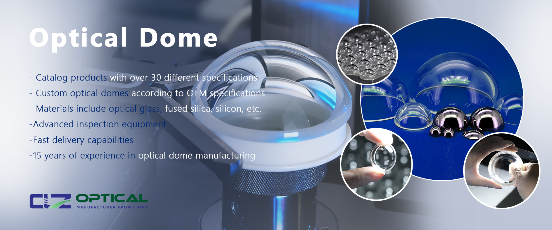
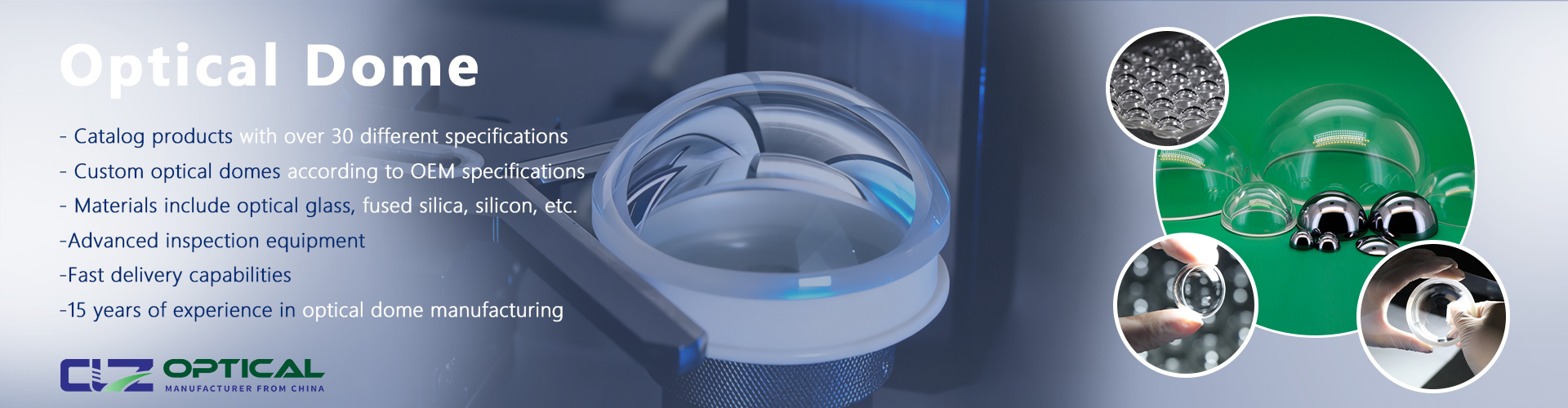
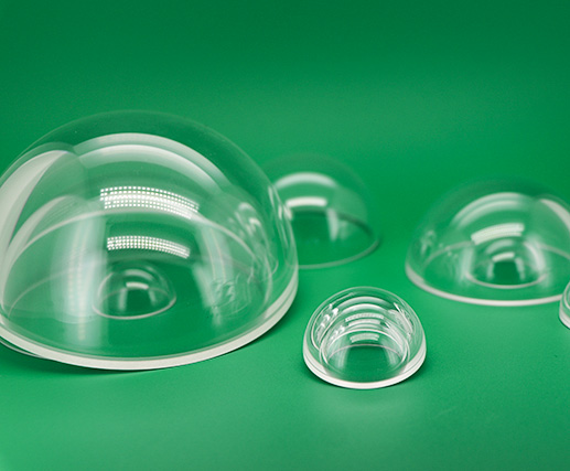
Optical Glass Domes can be adapted to unusual optical systems by changing their material, curvature, thickness, coating, and mounting position. This is useful for systems with off-axis sensors, wide fields of view, special wavelength requirements, compact housings, or harsh environments. For custom optical glass domes, engineers typically evaluate refractive index, ray tracing, and aberration correction before production.
Why Do Optical Glass Domes Need to Be Adapted?
Standard domes are not suitable for every optical system. Problems can occur when the camera is off-axis, the field of view is large, the wavelength is outside the visible range, or the dome must withstand pressure or temperature changes.
Key factors include:
Wavelength and optical transmission
Field of view (FOV)
Field of regard (FOR)
Sensor and entrance-pupil position
Dome curvature and thickness
Temperature and pressure
Required image quality
How Are Optical Glass Domes Adapted?
1. Define the Optical Requirements
Start with measurable specifications such as wavelength, FOV, sensor position, allowable distortion, transmission, temperature, pressure, and available installation space. This prevents the common mistake of selecting a dome based only on diameter.
2. Select the Optical Glass Dome Material
| Material | Approx. 50% Transmission Range |
|---|---|
| N-BK7 | 285–2800 nm |
| UV Fused Silica | 190–2750 nm |
| IR Fused Silica | 200–3600 nm |
| Sapphire | 190–5500 nm |
These are reference ranges. Actual transmission depends on material grade, thickness, wavelength, surface condition, and coating.
3. Modify the Optical Glass Dome Geometry
A hemispherical dome is not always the best option. Engineers can adjust the radius, height, wall thickness, and surface profile. Conformal optical domes, for example, can follow an aerodynamic housing more closely. However, geometry changes should be verified through optical simulation because they also change the light path and aberration behavior.
4. Adapt Optical Glass Domes for Off-Axis Sensors
When a camera is not aligned with the dome center, refraction can create nonlinear distortion. Underwater dome research has demonstrated that camera-to-dome decentering can significantly affect image geometry.
Possible solutions include changing the dome curvature, adjusting the sensor position, or adding optical correction.
5. Optimize the Dome for Aberration Correction
For advanced systems, the inner dome surface can be optimized to reduce aberrations. This can help improve performance without adding multiple corrective lenses, especially when system size and weight are limited.
6. Select the Optical Coating
Coatings can be selected for specific wavelength bands and applications. Anti-reflective coatings improve useful transmission, while hydrophobic or hard coatings may be useful in outdoor and harsh environments. Coating performance should be evaluated on the actual curved dome rather than assumed from flat-sample results.
What Is Needed to Design Custom Optical Glass Domes?
Optical Glass Dome Design Information
Outside diameter and dome height
Inner and outer radius
Center and edge thickness
Optical material
Operating wavelength
Surface quality and accuracy
Concentricity and thickness tolerance
Coating requirements
Temperature and pressure conditions
Mounting dimensions
For example, CLZ Optical reports concentricity and thickness irregularity below 0.02 mm for certain 40–50 mm radiometer domes and below 0.01 mm for certain 24–30 mm domes.
Optical Glass Dome Adaptation: Step-by-Step
Step 1: Map the Optical Path
Identify how light enters the dome, passes through its surfaces, reaches the lens, and arrives at the detector. Analyze the dome together with the complete optical system.
Step 2: Define the Spectral Range
Specify the actual wavelength range so the correct substrate and coating can be selected.
Step 3: Select the Dome Geometry
Use a conventional hemisphere for centered systems. Consider custom or conformal geometry for off-axis, aerodynamic, or wide-FOR systems.
Step 4: Set Thickness and Centration
Define numerical tolerances for thickness and concentricity. These parameters can affect the optical path and should be verified during manufacturing.
Step 5: Perform Optical Simulation
Use ray tracing to evaluate distortion, spot size, wavefront error, MTF, and off-axis performance. Zernike analysis can also help identify dome-induced aberrations.
Step 6: Manufacture and Test
Produce a prototype and compare measured results with simulation. Test transmission, surface accuracy, image quality, and coating performance under actual temperature or pressure conditions when required.
Real Application Case: Optical Glass Domes for Radiometers
Radiometers provide a practical example of precision dome adaptation. The dome protects the sensing system while allowing radiation to reach the detector. CLZ Optical reports certain 40–50 mm radiometer domes with concentricity and thickness irregularity below 0.02 mm.
This shows why a dome should be treated as part of the optical measurement system rather than only as a protective cover.
CLZ Optical Co., Ltd. provides customized optical dome solutions for radiometers, CCTV systems, and other specialized optical applications.
Common Optical Glass Dome Problems and Solutions
Problem 1: Image Distortion
Cause: Incorrect curvature, thickness variation, or sensor decentering.
Solution: Analyze the optical path and optimize the dome geometry and sensor position.
Problem 2: Poor Off-Axis Performance
Cause: Different refraction angles across the field of view.
Solution: Evaluate MTF, distortion, and wavefront error across the required FOV or FOR.
Problem 3: Performance Changes With Temperature
Cause: Thermal expansion, surface deformation, or refractive-index changes.
Solution: Include temperature in optical simulation and validation testing.
Problem 4: Good Transmission but Poor Image Quality
Cause: Transmission does not measure distortion or aberration.
Solution: Evaluate transmission together with MTF, surface accuracy, and wavefront performance.
Problem 5: Standard Dome Does Not Fit
Cause: Non-standard housing or mounting dimensions.
Solution: Use a custom dome designed around the actual mechanical and optical requirements.
How Should You Choose Optical Glass Domes?
Define the operating wavelength.
Determine the required FOV or FOR.
Confirm the sensor and entrance-pupil position.
Select the material and coating.
Define curvature and dimensional tolerances.
Simulate the complete optical path.
Prototype and test under real conditions.
For custom optical dome manufacturing, these requirements help the manufacturer optimize refractive index, ray tracing, and modulation transfer function (MTF) for the actual system.
FAQ About Optical Glass Domes
Can Optical Glass Domes Have Non-Standard Shapes?
Yes. Custom curvature and conformal profiles are possible, but their optical performance should be verified through simulation.
Can Optical Glass Domes Work With Off-Axis Sensors?
Yes. The sensor position must be included in the optical design to control distortion and aberration.
Which Material Is Best for Optical Glass Domes?
There is no universal best material. N-BK7, fused silica, and sapphire should be selected according to wavelength, environment, and optical requirements.
How Precise Do Optical Glass Domes Need to Be?
Precision depends on the application. Certain CLZ Optical radiometer domes are manufactured with thickness irregularity and concentricity below 0.02 mm.
Can Optical Glass Domes Be Used for Infrared Systems?
Yes. Suitable IR-transmitting materials and coatings can be selected according to the required wavelength band.
What Should I Send to an Optical Dome Manufacturer?
Provide the wavelength, FOV, sensor position, dome dimensions, material, tolerances, coating, environmental conditions, mounting requirements, and quantity. A CAD drawing or optical prescription is also useful.

Conclusion: Adapt the Optical Glass Dome to the System
The best way to adapt Optical Glass Domes to unusual systems is to design them as part of the complete optical path. Material, curvature, thickness, centration, coating, and mounting position all affect performance.
For radiometers, infrared sensors, underwater cameras, aerospace systems, and conformal optical systems, a customized dome can provide a better fit than a standard component. Define the requirements first, simulate the optical path, then manufacture and validate the dome under real operating conditions.
p>
Previous: None
Next: Why Are Smaller Optical Glass Domes Becoming More Common?