


Key Specifications Optical Buyers Should Know Before Ordering
Nov. 17, 2026
A lens can fit its mount and still miss the mark if its wavelength range, surface quality, or coating design does not match the system. This guide is for engineers, purchasing teams, and product designers checking optical component specifications before ordering. It explains how to state custom optical coating requirements and optical tolerances for precision optics, including angle of incidence (AOI), scratch-dig, and spectral transmittance. The aim is straightforward: give your supplier enough information to quote and manufacture the part you actually need.
Imagine a coated window arriving for a laser assembly, only for its transmission curve to shift at the real operating angle. Preventing that kind of costly mismatch starts with a complete drawing and a shared understanding of the terms behind it.
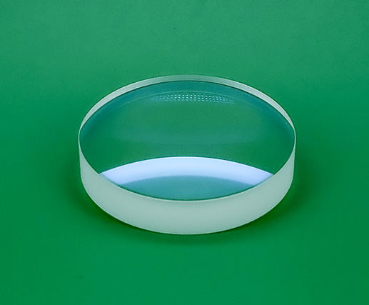
Optical specification basics: define the job before the part
An optical specification is a set of measurable requirements describing how a component is made and how it must perform. A drawing alone may show shape and dimensions, but it often leaves out operating wavelength, coating behavior, test conditions, and acceptance criteria.
Start with the system, not a catalog description. Record the light source, detector, beam geometry, temperature range, mounting method, and the component’s role. A protective window, imaging lens, and laser mirror may share a material but need very different surface and coating specifications.
- Wavelength range: State the minimum and maximum operating wavelengths, preferably in nanometers, and identify whether the source is narrowband, broadband, or pulsed.
- Incidence geometry: Give the angle of incidence (AOI) and whether the light is unpolarized, s-polarized, or p-polarized. Coating performance can change with both angle and polarization.
- Performance target: Specify transmission, reflection, absorption, or wavefront requirements, along with the wavelength interval and measurement conditions.
- Environment: Note temperature, humidity, vacuum exposure, cleaning method, and expected laser fluence where applicable.
These details turn a broad request for “an AR-coated window” into a requirement that can be designed, priced, tested, and accepted.
Optical material and dimensional tolerances to confirm
Material choice affects transmission, thermal behavior, weight, cost, and manufacturability. Fused silica is often selected for ultraviolet transmission and low thermal expansion; optical glasses such as BK7 are common in visible and near-infrared systems. The correct choice depends on the actual wavelength band, environment, and optical design—not simply on a material name copied from an older drawing.
For each component, specify the following dimensions and tolerances:
- Overall dimensions: Provide diameter or length and width, thickness, and tolerance. State units and identify the reference surfaces.
- Clear aperture: Define the usable optical area. A clear aperture of 90% of the diameter is common in some applications, but it should not be assumed; state the required value on the drawing.
- Wedge and parallelism: Wedge is the angle between the two faces; parallelism describes how closely they align. For a window used in an imaging path, excessive wedge may steer the beam or create unwanted deviation.
- Surface figure and flatness: Specify the measurement area and convention, such as peak-to-valley or RMS where relevant. “Flat” without a tolerance or test aperture is not an acceptance criterion.
- Bevels and edges: Give bevel size, edge condition, and any limits on chips. These details matter for handling, mounting, and coating coverage.
As a practical example, a 25 mm diameter window that must fit a cell may need a diameter tolerance, thickness tolerance, clear aperture, wedge limit, and edge treatment on its drawing. If the window is part of a precision imaging path, surface figure and transmitted wavefront error may matter more than a tight outside diameter.
Surface quality and scratch-dig for precision optics
Scratch-dig is a visual surface-quality classification, not a complete measure of optical performance. A designation such as 40-20 describes limits for visible scratches and digs under a specified inspection method. It does not, by itself, guarantee low scatter, low wavefront error, or suitability for a high-power laser.
Match the requirement to the function. A low-scatter laser optic may need tighter surface-defect limits than a protective cover. Conversely, demanding a premium scratch-dig grade on a non-imaging component can increase cost without improving system performance. If scatter is critical, state a scatter requirement or test method rather than relying only on a cosmetic grade.
Also distinguish surface figure from surface quality. Figure describes larger-scale shape error; scratch-dig addresses localized defects. Both may be needed, but they answer different questions.
Single-layer magnesium fluoride coating: what buyers should specify
A single-layer magnesium fluoride coating, often written MgF2, is a thin-film anti-reflection coating used on optical surfaces. At a chosen design wavelength, its physical thickness is commonly set near a quarter of the wavelength inside the film. For a 550 nm design wavelength and a refractive index near 1.38, the quarter-wave thickness is approximately 100 nm: 550 ÷ (4 × 1.38). Actual designs depend on the substrate, wavelength band, angle, and coating process.
MgF2 is used because its relatively low refractive index can reduce reflection in suitable designs. It does not automatically provide the same performance across every wavelength or angle, and a single layer is not a substitute for a multilayer coating when a demanding broadband specification is required. Ask for the designed spectral curve rather than assuming a coating labeled “AR” will meet a particular transmission target.
When requesting a single-layer magnesium fluoride coating, include these details:
- Wavelength or band: State the design wavelength or full operating interval. If performance is needed across a band, give the minimum acceptable transmission or maximum reflectance throughout it.
- Angle and polarization: Identify the AOI and polarization condition. If the optic will be used at several angles, provide the range.
- Coated surfaces: Specify one side or both sides, and identify any masked areas or uncoated edges.
- Substrate: Confirm the material and refractive index data used in the design, since the air-film-substrate interfaces determine the result.
- Durability and handling: State cleaning, humidity, temperature, and abrasion expectations. Ask what environmental or adhesion tests are included in the supplier’s standard process.
- Acceptance data: Request a coating curve or test report, and define the test wavelength range, AOI, and measurement tolerance.
For instance, “single-layer MgF2, 550 nm design wavelength, normal incidence, both surfaces” is a useful starting point, but it is not a full performance guarantee. Add the required reflectance or transmittance and the wavelength interval to make the acceptance condition clear.
Optical coating performance: transmission, reflection, and laser limits
Transmission and reflection are related but are not interchangeable specifications. For a transparent optic, incident energy may be transmitted, reflected, absorbed, or scattered. A useful coating requirement states which quantity matters and how it will be measured. If total transmission is critical, specify whether the value includes reflection losses and whether it applies to the complete component or a coated surface.
Laser users should also provide wavelength, pulse duration, repetition rate, beam size, and peak fluence or intensity. Laser-induced damage threshold (LIDT) depends on the test method and operating conditions, so a quoted value cannot be compared fairly unless those conditions are known. Do not infer a safe operating limit from a coating’s reflectance curve alone.
For imaging and interferometric systems, transmitted wavefront error, homogeneity, and stress birefringence may also be important. Include only the requirements that affect system performance, but define each one with a tolerance and test aperture.
Optical ordering checklist: steps from drawing to incoming inspection
A well-prepared request for quotation reduces clarification cycles and makes supplier offers easier to compare. Work through these steps before placing the order:
- Write the use case. Record the optic’s function, source and detector wavelengths, operating angle, environment, and expected power. This information guides material and coating selection.
- Complete the drawing. Add material, dimensions, tolerances, clear aperture, surface figure, scratch-dig, wedge, edge details, and coated surfaces. Identify the revision and units.
- Define coating performance. Give the wavelength band, AOI, polarization, and required transmission or reflectance. For a single-layer magnesium fluoride coating, name the design wavelength and state whether a measured curve is required.
- Set inspection and documentation needs. Specify certificates, coating reports, dimensional inspection, and any environmental or laser-damage testing. Agree on sampling or inspection coverage before production.
- Review the supplier’s quotation. Check that the quoted material, tolerances, coating, lead time, packaging, and exclusions match your request. Resolve any “standard” assumptions in writing.
- Plan incoming inspection. Use suitable tools: calipers or a micrometer for dimensions, an interferometer for surface figure where required, and a spectrophotometer for spectral transmission. Confirm that the instrument’s calibration and measurement setup match the stated acceptance conditions.
Consider a small production run of coated windows for a visible-light instrument. If the buyer provides only diameter and “AR coating,” the supplier must guess the material, band, angle, and performance target. A drawing that specifies those items, plus scratch-dig and clear aperture, makes the part verifiable on arrival and lowers the chance of a costly rework.
Advanced optical specification tips for better quotes
Once the core requirements are settled, a few practices can make procurement more efficient without weakening performance:
- Separate critical from preferred values. Mark must-meet tolerances distinctly from targets. This helps a supplier identify which manufacturing steps drive cost.
- Ask for a deviation review. If a supplier proposes an alternative glass, coating stack, or tolerance, request the expected effect on transmission, wavefront, and fit before approving it.
- Use functional test conditions. A coating measured at normal incidence may not represent an optic used at 45°. Match the test setup to the application where practical.
- Consider yield and quantity. Extremely tight tolerances can affect manufacturing yield and lead time. Ask which tolerance has the largest cost impact and whether a less restrictive value still meets the system budget.
- Protect the optic after manufacture. Specify individual packaging, clean handling, and any protective caps or separators needed to prevent contact damage in transit.
These checks are especially useful when comparing quotations. A lower price may reflect a different coating band, looser surface figure, or limited inspection—not necessarily a more efficient version of the same specification.
Choose optical components and coating support with CLZ
Before ordering, make sure the drawing and purchase specification agree on wavelength range, substrate, dimensions, surface quality, coating performance, and inspection conditions. Clear acceptance criteria help prevent avoidable delays and make incoming checks meaningful.
If you are selecting a single-layer magnesium fluoride coating or need help turning system requirements into an optical drawing, contact CLZ to discuss the component, operating conditions, and test documentation required. A complete request—including optical component specifications before ordering, custom optical coating requirements, and optical tolerances for precision optics—gives the supplier a practical basis for recommending and quoting the right solution.