A Basics of Optics (Ⅰ)
Jul. 25, 2022
Although “light” is something we are familiar with in our daily lives, its nature is hard for us to imagine. Light is nothing we can directly touch or manipulate. We can only learn about its properties via its interactions with matter.
A first elaborate description of light was developed in the seventeenth century. Classical geometric optics (ray optics) describes the propagation of light through and around objects by rays. In this model, light behaves like a projectile (or particle) whose flight path is influenced by interactions with media. So, this model focuses on the location and direction of light rays, while the intrinsic properties of light are ignored.
But already in the seventeenth century interference and diffraction effects had been observed in experiments and could not be explained in terms of geometric optics. Scientists like Christiaan Huygens (1629–1659) proposed that light has a wave-like character. With this approach, the laws of reflection and refraction could be explained. Wave optics was further improved by Thomas Young (1773–1829) and Augustin Fresnel (1788–1827) who introduced the interference principle for superposition of waves.
In the nineteenth century, Michael Faraday (1791–1867) and James Maxwell (1831–1879) extended the wave model. They discovered that light is an electromagnetic wave. This had far-reaching consequences particularly for the explanation of light–matter interaction. In this way, for instance, it was possible to explain the wavelength dependence of refraction. By this theory, visible (VIS) light became essentially the same physical phenomenon as microwaves, infrared (IR) radiation, ultraviolet (UV) radiation, and X-rays. The only difference is the corresponding wavelength. In 1888, the electromagnetic wave theory was experimentally verified by Heinrich Hertz (1857–1894).
It is quite interesting that the question of whether light is a particle or a wave is a recurring topic in history. Within the framework of quantum theory, Albert Einstein (1879–1955) proposed that light must have a momentum like small “solid” particles (photons). This assumption was based on the photoelectric effect which was a puzzling experiment that seemed to contradict the classic wave concept. In the early twentieth century, it became evident that the apparent dichotomy of the particle and wave descriptions in the macroscopic world is removed on the atomic scale. This is also known as the “wave-particle duality”. Quantum optics reveals that an intuitive understanding of light’s nature is beyond our imagination.
Four different approaches therefore exist to describe the behavior of light in optical systems, that is, geometric, wave, electromagnetic, and quantum optics. Depending on the given problem or application, we have to choose the adequate formalism which is most intuitive and feasible to describe the considered problem or application. For almost all purposes, geometric optics (Section A.1) and wave optics (Section A.2) are sufficient to understand most topics in ophthalmology and optometry.
A.1 Geometric Optics and Optical Imaging
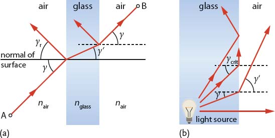
In geometric optics, light is treated as a bundle of rays which travels in optical media and obeys a set of geometric laws. As an example, let us consider a transparent, flat glass slide which is embedded in air as shown in Figure A.1a. When a light beam is incident on the left air–glass interface at an angle γ, some of it is reflected at an angle of
(A1) 
while the rest enters the glass body. The incoming, transmitted, and reflected rays all lie in the plane of incidence. The ray which enters the body now also changes its direction (γ′ ≠ γ). This effect is referred to as refraction. At the other interface, the ray is again partly reflected and partly transmitted. The transmitted portion is deflected to the other side so that it travels again at the angle γ.
Figure A.1 (a) Reflection, propagation, and transmission of a light ray which is incident from air on a flat glass slide. The ray is deflected at the air–glass interface towards the normal of the glass surface due to refraction. When the ray exits the medium, it is again deflected, but this time away from the normal of the surface. (b) Let us consider a light source inside glass. For γ < γcrit, the ray is again deflected as in (a). For γ = γcrit, the ray is deflected such that it travels along the glass surface. If γ > γcrit, we have total reflection at the air–glass interface, that is, the ray does not leave the glass volume anymore. Instead, it bounces back and forth between both interfaces.

A.1.1 Refraction and Dispersion
Why do incident rays change their direction at both air–glass interfaces? Obviously, it has something to do with the inherent properties of the medium. Here, Fermat’s principle gives a possible clue: light rays always choose the path which can be traversed in the least time. Keeping this in mind and looking again at Figure A.1a, we see that the light ray tries to minimize the traveling time in glass. Hence, glass seems to slow down the light rays. As a consequence, the fastest route from point A to point B requires the angle of travel to be changed (in our example: γ′ < γ).
The highest speed of light is found in vacuum, where light is as fast as c0 = 299 792 458 m/s. For all other media, no matter if they are gaseous, liquid, or solid, the speed decreases corresponding to the related refractive index n, that is, a dimensionless number greater than one. In an arbitrary medium with refractive index nm, the speed of light is cm = c0/nm. For example, we have cglass = c0/1.52 ≈ 2 × 10⁸ m/s in glass.
The angles of travel outside and inside a medium (γ and γ′, respectively) are directly related to the refractive index via Snell’s law. For the general case of an arbitrary medium (primed parameters) embedded in a host medium, Snell’s law reads
(A2) 
As long as γ is smaller than a critical angle
(A3) 
the situation is similar to the example given in Figure A.1a. For γ = γcrit, the refracted ray is exactly tangent to the interface. And if the angle of incidence exceeds the critical angle, the ray can no longer enter the adjacent medium. In the example of Figure A.1b, the ray is kept inside the glass slide in that it is reflected back at both interfaces without “losing” intensity. This so-called total (internal) reflection is actually a lossless effect which is used for optical fibers to transfer light over long distances.
At the interface of two different media, the refractive index determines not only the ray deflection, but also the fraction of light that is transmitted and reflected. For a normal incident light ray (γ = 0°) and neglected absorption, the reflected fraction (reflectance) is given by
(A4) 
and the transmitted fraction (transmittance) by
(A5) 
The relations (A4) and (A5) are referred to as the Fresnel equations. A more general form of the Fresnel equations for oblique incidence can be found in Section A.2.1.4.
Summing up, refraction occurs at every interface between two media with different refractive indices. The refractive index is in turn a function of the wavelength (color) of the incident light, which is referred to as dispersion. This phenomenon is caused by interactions (scattering and absorption) of light with atoms or molecules and is thus specific for each material.
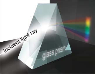
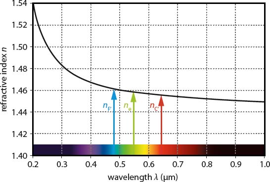
A well-known experiment to show the effect of dispersion is illustrated in Figure A.2, where a beam of white light shines onto a glass prism. Besides the overall refraction, the incident beam is split into the colors of the rainbow. Since the refractive index depends on the wavelength λ (Figure A.3), we have different refraction angles for each wavelength. As white light is composed of all visible colors, rays with different wavelengths are fanned out by the prism and eventually hit the wall at different positions. A medium whose refractive index decreases with increasing wavelengths (dn/dλ < 0) is said to have normal dispersion (as shown in Figure A.3), whereas the contrary case (dn/dλ > 0) is said to have anomalous dispersion.
Figure A.2 A typical experiment to demonstrate dispersion: white light which contains all color components of the visible spectrum is split into the colors of the rainbow by a glass prism.

Figure A.3 Refractive index of fused silica (SiO2) in the near-infrared, visible, and ultraviolet spectral range (color spectrum is shown for reference). The refractive index n(λ) changes considerably from violet (e.g., at 0.4 μm = 400 nm) to near-infrared wavelengths (e.g., at 1.0 μm = 1000 nm). To determine the Abbe number of fused silica, n is measured for certain wavelengths: n(λF′) = 1.4638, n(λe) = 1.4601, n(λC′) = 1.4567. From Eq. (A6), we obtain the Abbe number vsilica = 64.8.

Shining the light of an arc lamp onto a prism does not lead to a continuous color fan. In this case, we rather see discrete spectral lines which are separated by totally dark regions. Some of these material-specific emission lines are used to define a measure for dispersion in the visible spectral range, that is, the so-called Abbe number
(A6) 
nF′, ne, and nC′ correspond to the refractive indices of a considered medium at wavelengths λF′ = 480 nm, λe = 546 nm, and λC′ = 644 nm, respectively. Following Eq. (A6), we see that media with low dispersion have high values of v. Abbe numbers are particularly used to classify different sorts of glass and other optically transparent materials.
Previous: What Are IR Camera Lenses Made of?


